Quantcast
Channel: easy electronics projects – Electronics For You
Viewing all 48 articles
Browse latest View live

Mobile Sniffer

$
0
0

This mobile sniffer circuit can detect the use of a GSM mobile in mobile-phone-restricted areas such as examination halls and other ‘do not disturb’ areas. It can detect the activity of the phone from a distance of eight metres or more. The sniffer keeps monitoring the RF level in the area and gives warning indication if the RF level increases due to mobile phone activity. If two identical units of this sniffer are placed in the room, the range can be extended to a radius of 15-16 metres. The circuit can detect all forms of mobile phone activity even in the silent mode.

Circuit diagram for the mobile sniffer

The mobile sniffer circuit is designed as a sensitive RF detector. RF signal diode 1N34 forms the major element. Along with resistor R1 and capacitor C2, the diode picks up RF energy in the area. In the standby mode, the output from the diode is around 0.6 millivolt, which rises to 60 millivolts when it receives the high energy radiation from the mobile phone. Since the voltage level from the sensor diode is too weak, three-stage amplification is provided to give the warning indication through the speaker.
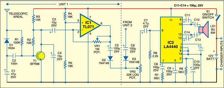
mobile sniffer circuit

Circuit working

Output pulses from the sensor diode (1N34) are preamplified by transistor BFR96 (T1). It is an RF/microwave low power transistor with high current gain and bandwidth. It has a high power gain of 14.5 dB at 0.5 GHz. Resistor R2 maintains the feedback and capacitor C4 keeps the collector voltage of T1 steady for maintaining the amplification.

The preamplified signals are fed to the second amplifier stage built around IC TL071 (IC1). It is a low-noise, JFET-input op-amp with low input bias and offset current. The BiFET technology provides fast slew rates to IC1. Here IC1 is designed as an inverting amplifier with resistor combination of R4 and R5 as potential divider to set half sup-ply voltage to its non-inverting input. The inverting input of IC1 receives the preamplified signals from T1. Variable resistor VR1 adjusts the feedback of the inverting amplifier and hence its gain.

The amplified signals from IC1 pass through capacitor C5 and diode D2 into volume control VR2. It also receives the signals from unit 2 identical to unit 1 through capacitor C6 and diode D3. From volume control VR2, power amplifier IC2 gets the amplified signals. IC LA4440 (IC2) is a two-channel audio power amplifier with inbuilt dual channels for stereo and bridge amplifier applications. In dual mode it gives 6W, and in bridge mode the output is 19W. It has good ripple rejection of 46 dB, small residual noise, built-in over-voltage and surge-voltage protection, and pin-to-pin protection. Here IC2 is wired in bridge configuration using only one input.

Is the circuit working?

Normally, a feeble hissing noise is heard from the speaker, indicating that the sniffer is active. The hissing noise is due to the detection of RF in the area. Its loudness can be adjusted using VR2. When a mobile phone is activated within the range of eight metres, a loud motor-boating sound is heard through the speaker. This is due to a very high RF activity during the activation of the mobile phone. The sound is louder if the mobile phone is within a radius of two metres.

Power to the mobile sniffer is derived from a 12V, 4.5Ah rechargeable battery, as AC power supply may generate audible disturbances in the circuit. A plug-in charger can be used to recharge the battery. Only one power supply with power amplifier is sufficient and the two units can be connected to the power amplifier. Use a good-quality 8-ohm, 6W speaker for LS1. RF reception and performance of the circuit depend on many factors, such as output power of the mobile phone, its orientation and position.

For a Nokia handset, the circuit receives RF signals from a distance of 8 metres and the speaker produces a loud enough warning signal.


 More fascinating projects available at electronics projects.

The post Mobile Sniffer appeared first on Electronics For You.


Temperature Control & Indicator System

$
0
0

Here is an easy-to-construct temperature indicator-cum-controller that can be interfaced with a heater’s coil to maintain the ambient room temperature. The temperature control system is based on Atmega8535 microcontroller, which makes it dynamic and faster, and uses an LCD module to display and two keys to increase or decrease the set values.

Temperature control system circuit
Fig. 1: Circuit of temperature indicator-cum-controller

Temperature control system circuit

Fig. 1 shows the circuit of the temperature indicator-cum-controller. It comprises microcontroller Atmega8535, temperature sensor LM35, regulator 7806, an LCD module and a few discrete components.

The 230V, 50Hz AC mains is stepped down by transformer X1 to deliver a secondary output of 9V, 500 mA. The transformer output is rectified by a full-wave bridge rectifier comprising diodes D1 through D4, filtered by capacitor C1 and regulated by IC 7806 (IC1). LED1 acts as the DC power indicator. Resistor R1 acts as the current limiter. A 4.8V rechargeable battery provides battery backup.

The ATmega8535 is a low-power CMOS 8-bit microcontroller based on the AVR enhanced RISC architecture. ATmega8535 has such features as 8 kB of in-system programmable flash memory (i.e., read-while-write capabilities), 512-byte EEPROM, 512-byte SRAM, 32 general-purpose input/output (I/O) lines, 32 general-purpose working registers, three flexible timers/counters with compare modes, internal and external interrupts, a serially programmable USART, a byte-oriented two-wire serial interface, an 8-channel, 10-bit analogue-to-digital converter (ADC) with optional differential input stage with programmable gain, a programmable watchdog timer with internal oscillator, an SPI serial port, and six software-selectable power-saving modes.

Fig. 2: Actual-size, single-side PCB for the temperature indicator-cum-controller
Fig. 3: Component layout for the PCB

Download PCB and component layout PDFs: click here

The post Temperature Control & Indicator System appeared first on Electronics For You.

Make Your Controllers For Any Game Using Arduino: DIY

$
0
0

Nowadays, we have lots of game controllers that are improving the gaming experience over the years. There are number of factors responsible for a game to get a good fan base. Graphics quality, story line, the way in which user interacts with the game etc., Gaming experience can be improved to a good extent with the help of controllers, but these controllers are quite expensive. Have you ever thought of making your own controllers for games? This project takes you through a series of simple steps to help you make your own game controller using Arduino for any games you want to play. This project designs a throttle system for Microsoft flight simulator.


The first image is the game controller using Arduino, designed for flight simulator. It has a throttle system, control switches (Lights, landing gear control, APU Switches and seat-belts ON/OFF).

Concept of the game controller

This project explains the concept of the game controller with help of a flight simulator game. In this game, to speed up the flight that to increase the engine speed we use F3 key for gradual set by step increase or F4 key for max throttle and F2 for gradual step by step decrease or F1 for Idle throttle. We are going to programmatically trigger the corresponding keys based on some conditions.

This project uses an ULTRASONIC SENSOR to measure the distance between the sensor and the obstacle (say a cardboard box) in front of it. We use an Arduino board to get the distance value and send it in serial to pc in a specific COM port. In order to program the Arduino we need Arduino IDE.

Distance (unit inches) – Approximately 73.7 microseconds per inch (i.e. sound travels at 1130 feet per second).  This gives the distance travelled by the wave from the sensor to the obstacle and again back to sensor, so we divide by 2 to get the distance of the obstacle.

The HC-SR04 module produces duration in microseconds as the output that the time taken to receive the echo. The following convention is used to convert the distance (inches) in place of duration:

Distance = duration / 74 / 2

Next we design a small application that reads this serial value and programmatically triggers the keys based on the following condition.

if past distance < new distance (this condition is satisfied is the obstacle is moved towards the sensor)

tigger F3

else if past distance > new distance (this condition is satisfied if the obstacle is moved away from the sensor)

trigger F2

else if new distance > max_idle_limit

trigger F1 key once and release all the keys

else if new_distance <= max_speed_limit

trigger F4 once and release all the keys

else (i.e. when the past = new distance)

there is no movement

release all the keys

The above conditions are tested for each and every distance value sent by the Arduino board in serial port. This application should run in parallel to the game for which the controller is designed.

flowchart for game controller using arduino


Components & Software Required

  • Arduino: This project uses Arduino UNO R3. If you have Arduino Leonard/Due board then there is no need to making the software in C# since the board has its own keyboard libraries for triggering keys.
  • Ultrasonic Sensor HC-SR04
  • Jumper Wires
  • Arduino IDE
  • Visual Studio IDE

Circuit diagram

  • circuit diagram for game controller using arduino
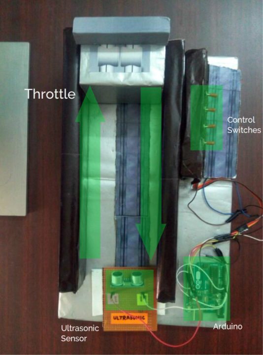
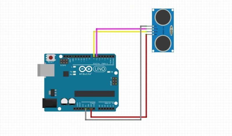
Arduino Board pin 7 – Echo Pin Ultrasonic Sensor
  • Arduino Board pin 6 – Triger Pin Ultrasonic Sensor
  • 5V – Vcc of Ultrasonic sensor
  • Gnd pin to GND of ultrasonic sensor

If you want add more functionalities to game, add some toggle switches and button to some other pins and you can listen and respond to them by treating them as interrupts. But now lest don’t complicate this ill just take you through the basic setup.

The post Make Your Controllers For Any Game Using Arduino: DIY appeared first on Electronics For You.

Door Guard

$
0
0

This door guard uses operational amplifier µA741 and a light-dependent resistor (LDR). Operational amplifier µA741 is used as a sensitive voltage comparator. Preset VR1 provides reference voltage to the non-inverting terminal (pin 3) of µA741. LDR1 and resistor R1 are connected to inverting pin 2 of IC1. LED1 and LDR1 are installed at opposite sides of entry such that light from LED1 falls on LDR1.

door guard circuit

When LED light is falling on LDR1, its resistance goes low in comparison to R1 and as a result pin 2 of IC1 goes high. Consequently, output pin 6 of IC1 goes low and LED2 blinks while piezobuzzer PZ1 stops sounding. This indicates that the gate is closed.

When anyone opens the gate to enter or exit, the light from LED1 falling on LDR 1 is obstructed and its resistance goes very high. As a result, pin 2 of IC1 goes low and output pin 6 of IC1 goes high. LED2 stops blinking while the piezobuzzer sounds. This indicates that the gate is open.

The project kit is available at grab.electronicsforu.com.


More interesting projects available here.

The post Door Guard appeared first on Electronics For You.

FM Booster

$
0
0

An antenna amplifier boosts a radio signal considerably for devices that receive radio waves. Many devices have an RF amplifier stage in their circuitry, that amplifies the antenna signal. The received signal is usually very low in amplitude and is not enough for the receiver circuitry, hence the signal booster. In this project, we discuss a FM booster that can be used to listen to programs from distant FM stations clearly.

FM booster circuit assembly

The circuit comprises a common-emitter tuned RF pre-amplifier wired around VHF/UHF transistor 2SC2570. (Only C2570 is annotated on the transistor body.) Assemble the circuit on a good-quality PCB (preferably, glass-epoxy). Adjust input/ output trimmers (VC1/VC2) for maximum gain.

fm booster
FM Booster circuit

Input coil L1 consists of four turns of 20SWG enamelled copper wire (slightly space wound) over 5mm diameter former. It is tapped at the first turn from ground lead side. Coil L2 is similar to L1, but has only three turns. Pin configuration of transistor 2SC2570 is shown in the figure.

The project kit is available at grab.electronicsforu.com.


More interesting projects available here.

The post FM Booster appeared first on Electronics For You.

Numeric Water Level Indicator

$
0
0

Most water level indicator for water tanks are based upon the number of LEDs that glow to indicate the corresponding level of water in the container. Here we present a digital version of the water-level indicator. It uses a 7-segment display to show the water level in numeric form from’0′ to ‘9’.

Water level indicator circuit diagram

water level indicator circuit
Water level indicator circuit

The circuit works off 5V regulated power supply. It is built around priority encoder IC 74HC147 (IC1), BCD-to-7-segment decoder IC CD4511 (IC2), 7-segment display LTS543 (DIS1) and a few discrete components. Due to high input impedance, IC1 senses water in the container from its nine input terminals. The inputs are connected to +5V via 560-kilo-ohm resistors. The ground terminal of the sensor must be kept at the bottom of the container (tank). IC 74HC147 has nine active-low inputs and converts the active input into active-low BCD output. The input L-9 has the highest priority.


The outputs of IC1 (A, B, C and D) are fed to IC2 via transistors T1 through T4. This logic inverter is used to convert the active-low output of IC1 into active-high for IC2. The BCD code received by IC2 is shown on 7-segment display LTS543. Resistors R18 through R24 limit the current through the display.

Operation & working

When the tank is empty, all the inputs of IC1 remain high. As a result, its output also remains high, making all the inputs of IC2 low. Display LTS543 at this stage shows ‘ 0, ‘ which means the tank is empty. Similarly, when the water level reaches L-1 position, the display shows ‘1, ‘and when the water level reaches L-8 position, the display shows ‘8.’ Finally, when the tank is full, all the inputs of IC1 become low and its output goes low to make all the inputs of IC2 high. Display LTS543 now shows ‘9,’ which means the tank is full.


Assemble the circuit on a general-purpose PCB and enclose in a box. Mount 7-segment LTS543 on the front panel of the box. For sensors L-1 though L-9 and ground, use corrosion-free conductive-metal (stainless-steel) strips.

The project kit is available at grab.electronicsforu.com.


More interesting projects available here.

The post Numeric Water Level Indicator appeared first on Electronics For You.

PC Based Timer

$
0
0

Timers are very useful both for industrial applications and household appliances. Here is a PC based timer that can be used for controlling the appliances for up to 18 hours. For control, the timer uses a simple program and interface circuit. It is very cost-effective and efficient for those who have a PC at workplace or home. The tolerance is ±1 second.

PC based timer circuit

PC based timer circuit

The circuit for interfacing the PC’s parallel port with the load is very simple. It uses only one IC MCT2E, which isolates the PC and the relay driver circuits. The IC prevents the PC from any short circuit that may occur in the relay driver circuit or appliance. The glowing of LED1 indicates that the appliance is turned on. Transistor BC548 is used as the relay driver.

The program code is written in ‘C’ language and compiled using ‘Turbo C’ compiler. When the program is run, it prompts the user to input the time duration in seconds or minutes to control the appliance. After entering the required timing, press any key from the keyboard.

Suppose you input the total duration as ‘x’ minutes, of which ‘on’ and ‘off’ durations are ‘y’ and ‘z’ minutes, respectively. The program will repeat the on-off cycle for x/(y+z) number of times. After completion of the total time, to repeat the cycle, you will have to reset the time in the program to activate the circuit.

The program uses two bytes for storing integer type data. So when input is given in terms of seconds or minutes, it can hold 216–1=65,535 seconds or 18 hours at the maximum. The sleep() function in the program is used to hold the appliance in ‘on’ or ‘off’ condition for the ‘on’ and ‘off’ periods as entered by the user against prompts. The sound() function is used to give a beep during ‘on’ condition of the appliance.

Download source code: click here

86A_TIMER

The project kit is available at grab.electronicsforu.com.


More interesting projects available here.

The post PC Based Timer appeared first on Electronics For You.

Long Range FM Transmitter

$
0
0

Several circuits for constructing FM transmitter have been published in EFY. The power output of most of these circuits were very low because no power amplifier stages were incorporated.

The transmitter circuit described here has an extra RF power amplifier stage, after the oscillator stage, to raise the power output to 200-250 milliwatts. With a good matching 50-ohm ground—plane antenna or multi-element Yagi antenna, this transmitter can provide reasonably good signal strength up to a distance of about 2 kilometres.

FM Transmitter Circuit & Working

Long range FM transmitter
FM transmitter circuit

The circuit built around transistor T1 (BF494) is a basic low-power variable- frequency VHF oscillator. A varicap diode circuit is included to change the frequency of the transmitter and to provide frequency modulation by audio signals. The output of the oscillator is about 50 milliwatts. Transistor T2 (2N3866) forms a VHF-class A power amplifier. It boosts the oscillator signals’ power four to five times. Thus, 200-250 milliwatts of power is generated at the collector of transistor T2.

For better results, assemble the circuit on a good-quality glass epoxy board and house the transmitter inside an aluminium case. Shield the oscillator stage using an aluminium sheet Coil winding details are given below:

L1 – 4 turns of 20 SWG wire close wound over 8mm diameter plastic former.

L2 – 2 turns of 24 SWG wire near top end of L1.

(Note: No core (i.e. air core) is used for the above coils)

L3 – 7 turns of 24 SWG wire close wound with 3mm diameter air core.

L4 – 7 turns of 24 SWG wire-wound on a ferrite bead (as choke)

Potentiometer VR1 is used to set the centre frequency whereas potentiometer VR2 is used for power control. For hum free operation, operate the transmitter on a 12V rechargeable battery pack of 10 x 1.2-volt Ni-Cd cells. Transistor T2 must be mounted on a heat sink. Do not switch on the transmitter without a matching antenna. Adjust both trimmers (VC1 and VC2) for maximum transmission power. Adjust potentiometer VR1 to set the centre frequency near 100 MHz.

This transmitter should only be used for educational purposes. Regular transmission using such a transmitter without a licence is illegal in India.

The project kit is available at grab.electronicsforu.com.


More interesting projects available here.

The post Long Range FM Transmitter appeared first on Electronics For You.


Smart Emergency Light

$
0
0

An emergency light can come in handy at all sorts of time, especially when there’s a power outage. Now you need not fear dark nights when power breaks down. Here’s a white LED-based smart emergency light that automatically turns on when mains power supply fails.

Emergency light working

The circuit consists of power supply, battery charger and switching sections. The power supply and charger sections are built around transformer X1, diodes D1 and D2, transistor T1, resistors R1 and R2, and zener diode ZD1. The power supply for the circuit is derived from AC mains by using 9V-0-9V, 250mA step-down transformer X1. Diodes D1 and D2 rectify the AC voltage into DC voltage, which is smoothed by filter capacitor C1. The unregulated DC voltage is regulated by transistor T1 along with resistor R1 and zener diode ZD1. The regulated DC voltage, via resistor R2, charges the lead-acid battery. Diode D3 connects the battery power supply to the switching circuit when mains power is unavailable.

Circuit diagram

emergency light circuit
Emergency Light Circuit

The switching circuit is built around an NE555 timer (IC1), which is wired in monostable mode. When a low voltage is applied at trigger pin 2 of IC1, the timer activates and its output pin 3 goes high. It remains in that state until IC1 is triggered again at its pin 2.

Light-dependant resistor LDR1 is connected between the positive supply of the battery and trigger pin 2 of IC1. Resistor R3 is connected between pin 2 of IC1 and ground. The resistance value of LDR1 remains high in dark (at night) and low in ambient light (in daytime). This phenomenon is utilised to control the switching circuit.

Circuit operation

Working of the circuit is simple. In daytime, when ambient light falls on LDR1, its resistance decreases to make trigger pin 2 of IC1 high. As a result, output pin 3 goes low and the LEDs (LED1 through LED7) remain off.

At night (in the dark), the resistance of LDR1 increases and a low voltage is applied to trigger pin 2 of IC1. This activates the monostable and its output goes high to make all the LEDs glow.

When mains power is available, reset pin 4 of IC1 is grounded via transistor T2 and its output pin 3 remains low. As a result, the LEDs don’t glow. When mains power fails, transistor T2 does not conduct and reset pin 4 of IC1 gets positive supply through resistor R5. As a result, the output of IC1 goes high to light up the LEDs. Due to pulsating DC output at pin 3 of IC1, it can drive seven LEDs (LED1 through LED7).

Assemble the circuit on a general-purpose PCB and enclose in a cabinet with enough space for the battery. Mount the seven white LEDs on the front panel of the box. Fix LDR1 away from the white LEDs to prevent their light from falling on LDR1.

The project kit is available at grab.electronicsforu.com.


More interesting projects available here.

The post Smart Emergency Light appeared first on Electronics For You.

Automatic School Bell

$
0
0

Consider that a school has a total of eight periods with a lunch break after the fourth period. Each period is 45 minutes long, while the duration of the lunch break is 30 minutes. To ring this automatic school bell to start the first period, the peon needs to momentarily press switch S1. Thereafter, the bell sounds every 45 minutes to indicate the end of consecutive periods, except immediately after the fourth period, when it sounds after 30 minutes to indicate that the lunch break is over. When the last period is over, LED2 glows to indicate that the bell circuit should now be switched off manually.

automatic school bell circuit

In case the peon has been late to start the school bell, the delay in minutes can be adjusted by advancing the time using switch S3. Each pushing of switch S3 advances the time by 4.5 minutes. If the school is closed early, the peon can turn the bell circuit off by momentarily pressing switch S2.The bell circuit contains timer IC NE555 (IC1), two CD4017 decade counters (IC2 and IC3) and AND gate CD4081 (IC4). Timer IC1 is wired as an astable multivibrator, whose clock output pulses are fed to IC2.

IC2 increases the time periods of IC1 (4.5 and 3 minutes) by ten times to provide a clock pulse to IC3 every 45 minutes or after 30 minutes, respectively. When the class periods are going on, the outputs of IC3 switch on transistors T1 and T2 via diodes D4 through D12.

Resistors R4 and R5 connected in series to the emitter of npn transistor T2 decide the 4.5-minute time period of IC1. The output of IC1 is further connected to pin 14 of IC2 to provide a period with a duration of 45 minutes. Similarly, resistors R2 and R3 connected in series to the emitter of npn transistor T1 decide the 3-minute time period of IC1, which is further given to IC2 to provide the lunch-break duration of 30 minutes.

Initially, the circuit does not ground to perform its operation when 12V power supply is given to the circuit. When switch S1 is pressed momentarily, a high enough voltage to fire silicon-controlled resistor SCR1 appears at its gate. When SCR1 is fired, it provides ground path to operate the circuit after resetting both decade counters IC2 and IC3. At the same time, LED1 glows to indicate that school bell is now active.

The post Automatic School Bell appeared first on Electronics For You.

Sunset Lamp

$
0
0

LDR-based automatic lights flicker due to the change in light intensity at dawn and dusk. So compact fluorescent lamps (CFLs) are unsuitable in such circuits as flickering may damage the electronic circuits within these lamps. The sunset lamp circuit described here can solve the problem and switch on the lamp instantly when the light intensity decreases below a preset level.

Sunset Lamp circuit description

This sunset lamp circuit uses popular timer IC NE555 (IC1) as a Schmitt trigger to give the bistable action. The set and reset functions of the comparators within the NE555 are used to give the instantaneous action. The upper threshold comparator of IC1 trips at 2/3Vcc, while the lower trigger comparator trips at 1/3Vcc. The inputs of both the threshold comparator and the trigger comparator of NE555 (pins 6 and 2) are tied together and connected to the voltage divider formed by LDR1 and VR1. The voltage across LDR1 depends on the light intensity.

In daylight, LDR1 has low resistance and the input voltage to the threshold comparator goes above 2/3Vcc and its output becomes zero, which resets the internal flip-flop of IC1. But the input to the trigger comparator is still more than 1/3Vcc, which keeps output pin 3 of IC1 low. Triac BT136 connected to output pin 3 of IC1 remains quiescent due to insufficient value of current for firing it. Thus lamp L1 remains ‘off’ during daytime.

sunset lamp circuit
Sunset Lamp Circuit

Circuit operation

At sunset, the resistance of LDR1 increases, and the voltage at the input of the threshold comparator decreases below 2/3Vcc and that of the trigger comparator goes below 1/3Vcc. As a result, the outputs of threshold and trigger comparators go high, which sets the flip-flop. This changes output pin 3 of IC1 from low to high. Triac1 gets the necessary gate current through resistor R2 and fires. Thus it completes the power supply to the lamp through Triac1. LED1 glows to indicate the high output state of IC1.

Power supply to the circuit is directly derived from the mains through capacitor C4. This capacitor delivers current in the circuit. Diodes D1 and D2 rectify the AC from capacitor C4 and capacitor C3 provides the necessary smoothing. Zener diode ZD1 provides rectified 15V DC for the circuit. Bleeder resistor R4 removes the stored voltage of the capacitor when the circuit is unplugged.

Assemble the circuit on any general-purpose PCB and enclose in a plug-in type adaptor box. Connect the live and neutral points to the pins of the adaptor box. Provide in the box 5mm holes for LDR1 and LED1. Plug the unit at a place where daylight is sufficient to inhibit the circuit operation during daytime. Light from the lamp should not fall on LDR1 at night.

Caution: The circuit carries 230V AC and most of its points are at mains lethal potential. So do not touch any point in the circuit when it is powered and adjust the preset only with a plastic or insulated screwdriver.

The project kit is available at grab.electronicsforu.com.


More interesting projects available here.

The post Sunset Lamp appeared first on Electronics For You.

Speed Control of DC Motor Using Pulse-Width Modulation

$
0
0

Pulse-width modulation (PWM) or duty-cycle variation methods are commonly used in speed control of DC motors. The duty cycle is defined as the percentage of digital ‘high’ to digital ‘low’ plus digital ‘high’ pulse-width during a PWM period. Fig. 1 shows the 5V pulses with 0% through 50% duty cycle.

Fig 1 : Pluses with 0% through 50% duty cycle

The average DC voltage value for 0% duty cycle is zero; with 25% duty cycle the average value is 1.25V (25% of 5V). With 50% duty cycle the average value is 2.5V, and if the duty cycle is 75%, the average voltage is 3.75V and so on. The maximum duty cycle can be 100%, which is equivalent to a DC waveform. Thus by varying the pulse-width, we can vary the average voltage across a DC motor and hence its speed.

Circuit Diagram

The circuit of a simple speed controller for a mini DC motor, such as that used in tape recorders and toys, is shown in Fig. 2.

Fig 2 : DC Motor speed control using PWM method

Circuit Operation

Here N1 inverting Schmitt trigger is configured as an astable multivibrator with constant period but variable duty cycle. Although the total in-circuit resistance of VR1 during a complete cycle is 100 kilo-ohms, the part used during positive and negative periods of each cycle can be varied by changing the position of its wiper contact to obtain variable pulse-width. Schmitt gate N2 simply acts as a buffer/driver to drive transistor T1 during positive incursions at its base. Thus the average amplitude of DC drive pulses or the speed of motor M is proportional to the setting of the wiper position of VR1 potmeter. Capacitor C2 serves as a storage capacitor to provide stable voltage to the circuit.

Thus, by varying VR1 the duty cycle can be changed from 0% to 100% and the speed of the motor from ‘stopped’ condition to ‘full speed’ in an even and continuous way. The diodes effectively provide different timing resistor values during charging and discharging of timing capacitor C1.

Fig3 :Pin Configuration of BC337A

The pulse or rest period is approximately given by the following equation:Pulse or Rest period ≈ 0.4 x C1 (Farad) x VR1 (ohm) seconds. Here, use the in-circuit value of VR1 during pulse or rest period as applicable.

The frequency will remain constant and is given by the equation:

Frequency ≈ 2.466/(VR1.C1) ≈ 250 Hz (for VR1=100 kilo-ohms and C1=0.1 µF)

The recommended value of in-circuit resistance should be greater than 50 kilo-ohms but less than 2 mega-ohms, while the capacitor value should be greater than 100 pF but less than 1 µF.

More interesting projects available here.


The post Speed Control of DC Motor Using Pulse-Width Modulation appeared first on Electronics For You.

Water-level Controller

$
0
0

In most houses, water is first stored in an underground tank (UGT) and from there it is pumped up to the overhead tank (OHT) located on the roof. People generally switch on the pump when their taps go dry and switch off the pump when the overhead tank starts overflowing. This results in the unnecessary wastage and sometimes non-availability of water in the case of emergency. This water-level controller circuit makes this system automatic. It switches on the pump when the water level in the overhead tank goes low and switches it off as soon as the water level reaches a pre-determined level. It also prevents ‘dry run’ of the pump in case water level in underground tank goes below suction level.

In this water-level controller circuit, the common probes connecting the underground tank and the overhead tank to +9V supply are marked ‘C’. The other probe in underground tank, which is slightly above the ‘dry run’ level, is marked ‘S’. The low-level and high-level probes in the overhead tank are marked ‘L’ and ‘H’, respectively.

Water-level controller circuit

Water-level Controller Circuit
Water-Level Controller Circuit

When there is enough water in the underground tank, probes C and S are connected through water. As a result, transistor T1 gets forward biased and starts conducting. This, in turn, switches transistor T2 on. Initially, when the overhead tank is empty, transistors T3 and T5 are in cut-off state and hence pnp transistors T4 and T6 get forward biased via resistors R5 and R6, respectively.

As all series connected transistors T2, T4, and T6 are forward biased, they conduct to energize relay RL1 (which is also connected in series with transistors T2, T4, and T6). Thus the supply to the pump motor gets completed via the lower set of relay contacts (assuming that switch S2 is on) and the pump starts filling the overhead tank.

Once the relay has energised, transistor T6 is bypassed via the upper set of contacts of the relay. As soon as the water level touches probe L in the overhead tank, transistor T5 gets forward biased and starts conducting. This, in turn, reverse biases transistor T6, which then cuts off. But since transistor T6 is bypassed through the relay contacts, the pump continues to run. The level of water continues to rise.

Circuit Operation

When the water level touches probe H, transistor T3 gets forward biased and starts conducting. This causes reverse biasing of transistor T4 and it gets cut off. As a result, the relay de-energises and the pump stops. Transistors T4 and T6 will be turned on again only when the water level drops below the position of L probe.

Presets VR1, VR2, and VR3 are to be adjusted in such a way that transistors T1, T3, and T5 are turned on when the water level touches probe pairs C-S, C-H, and C-L, respectively. Resistor R4 ensures that transistor T2 is ‘off’ in the absence of any base voltage. Similarly, resistors R5 and R6 ensure that transistors T4 and T6 are ‘on’ in the absence of any base voltage. Switches S1 and S2 can T4 and T6 are ‘on’ in the absence of any base voltage. Switches S1 and S2 can be used to switch on and switch off, respectively, the pump manually.

Project Installation

A8C_Water-level-controller-1_-efy
Water-level controller application

You can make and install probes on your own as per the requirement and facilities available. However, we are describing here how the probes were made for this prototype.

The author used a piece of nonmetallic conduit pipe (generally used for domestic wiring) slightly longer than the depth of the overhead tank. The common wire C goes up to the end of the pipe through the conduit. The wire for probes L and H goes along with the conduit from the outside and enters the conduit through two small holes bored into it as shown above.

Care has to be taken to ensure that probes H and L do not touch wire C directly. Insulation of wires is to be removed from the points shown. The same arrangement can be followed for the underground tank also. To avoid any false triggering due to interference, a shielded wire may be used.


More interesting projects available here.

The post Water-level Controller appeared first on Electronics For You.

Ethernet Interface for Automation Systems

$
0
0

Communication with remotely located automation systems is possible via the Internet. A physical communication port with a network is required for this communication. An Ethernet interface can be used for that purpose. Presented here is the design and implementation of an Ethernet interface for automation system, using a microcontroller.

Ethernet is quite a complex interface, which was difficult to use with small microcontrollers having little memory—until Microchip came up with ENC28J60 Ethernet chip. It is a small chip with only 28 pins that can be used as an Ethernet network interface for any microcontroller equipped with serial peripheral interface (SPI).

Fig. 1: html page embedded in the code

Therefore Microchip opens a whole new world of applications like the one we have implemented in this project where real-time readings of temperature and ambient light sensors placed at a remote place can be read using the Internet.

Fig. 1 shows the html page embedded in the source code of the automation system that provides these readings. The html page can be accessed from a remote location. Distance is no longer a limiting factor. Even Wi-Fi connectivity is possible because the devices can be connected to a wireless bridge too.

Fig. 2: Block diagram of automation system

Circuit and working
Fig. 2 shows the block diagram of the overall automation system. The temperature and light intensity are continuously monitored by two sensors that communicate with the microcontroller unit via I2C protocol. The relay is activated based on the readings from the ambient light sensor. Real-time reading from the sensors and the trigger status, for example the status of temperature, are continuously displayed on the LCD.

The automation system is connected to the router using Ethernet interface. The html page embedded in the code is continuously updated with real-time readings of both the sensors as shown in Fig. 1.

Fig. 3 shows the circuit built around microcontroller ATmega128 (IC3), Ethernet controller ENC28J60 (IC4), regulators 7805 and LM1117 (IC1 and IC2), digital-out temperature sensor TMP275 (IC5), miniature ambient light photo-sensor APDS9300 (IC6) and a few discrete components.

Ethernet interface. The ENC28J60 is a standalone Ethernet controller with an industry-standard SPI interface. It is designed to serve as an Ethernet network interface for any controller equipped with SPI. The ENC28J60 meets all the IEEE 802.3 specifications. It incorporates a number of packet filtering schemes to limit incoming packets. It also provides an internal DMA module for fast data through-put and hardware-assisted checksum calculation, which is used in various network protocols.

Fig. 3: Circuit built around microcontroller ATmega128

Communication with the host controller is implemented via SPI, with clock rates of up to 25 MHz. Two dedicated pins (LED A and LED B) are used for LED link and network activity indication. Fig. 4 shows the simplified connections scheme for easy understanding.

The SPI pins of IC3 are directly interfaced with IC4 as shown in Fig. 4. In the interconnection circuit there is no conversion required from 3.3 V to 5 V because the pins of IC4 are 5V tolerant.

Automation system. The heart of the system is ATmega128, which is an eight-bit microcontroller with 128 kB of in-system programmable Flash with read-while-write capabilities, 4kB EEPROM, 4kB SRAM, 53 general-purpose input/output (I/O) lines, 32 general-purpose working registers, real-time counter (RTC), four flexible timers/counters with compare modes and PWM, two US-ARTs, a byte-oriented two-wire serial interface, an eight-channel, 10-bit analogue-to-digital converter (ADC) with optional differential input stage with programmable gain, programmable watchdog timer with internal oscillator, an SPI serial port, IEEE 1149.1 standard-compliant JTAG test interface (also used for accessing the on-chip debug system and programming) and six software-selectable power-saving modes.

9AE_test-point

Microcontroller IC3 continuously monitors temperature and light intensity using sensors IC5 and IC6, respectively. Both the sensors communicate to the microcontroller via I2C protocol. Port pins PD0 and PD1 are used to interface both the sensors to the microcontroller. Real-time readings from both the sensors are displayed on LCD1, which is interfaced to IC3 using pins PC4 through PC7 for data pins of LCD1 and pins PC0 through PC2 for control pins of LCD1. Temperature range can be defned in the source code, within which LCD1 displays the message ‘it’s normal temperature’ and green LEDs (LED5 and LED8) glow. If temperature crosses the maximum of the range, the message on the display changes to ‘it’s too hot’ and red LEDs (LED3 and LED6) glow. In case temperature goes below the minimum limit, the message changes to ‘it’s too cold’ and blue LEDs (LED4 and LED7) glow.

The post Ethernet Interface for Automation Systems appeared first on Electronics For You.

Periodically On-Off Mosquito Repellent

$
0
0

Some of the mosquito repellent available in the market use a toxic liquid to generate poisonous vapours in order to repel mosquitoes out of the room. Due to the continuous release of poisonous vapours into the room, after midnight the natural balance of the air composition for good health reaches or exceeds the critical level. Mostly, these vapours attack the brain through lungs and exert an anesthetic effect on mosquitoes as well as other living beings by small or greater percentage. Long exposure to these toxic vapours may cause neurological or related problems.

Mosquito Repellent Circuit

Mosquito repellent circuit

Here is a circuit that automatically switches on and off the mosquito repellent after preset time interval, thus controlling the release of toxic vapours into the room.

The circuit turns the mosquito repellent periodically ‘on’ and ‘off’ for approximately 20 minutes each. So if you leave the mosquito repellent switched on from 10 pm to 6 am (eight hours), it will be ‘on’ for four hours and ‘off’ for four hours of the total duration. During ‘off’ time, the room air tries to balance its natural composition. Another important feature is that the circuit switches to ‘on’/‘off’ operation without producing any noise or a sound click as in a relay and hence doesn’t disturb your sleep.

The circuit consists of a timer section built around IC 555 (IC1) and an automatic switching section using triac BT136 (TRIAC1). Power supply to the circuit is derived from the AC mains by stepping it down to a required level and rectifying it. The elimination of the transformer saves on space as well as money. Zener diode ZD1 and capacitor C2 provide regulated 9V DC power supply to timer IC1.

The timer section comprises resistors R1 and R2 and capacitor C1. The output of timer IC 555 is fed to the gate terminal of BT136 through series LED1 and resistor R4. When the timer output goes high, it triggers the gate of TRIAC1 and LED1 shows the ‘on’ period. During ‘off’ time, the output of IC1 goes low and hence TRIAC1 is not fired and LED1 doesn’t glow.

The circuit is very compact and can be assembled on a general-purpose PCB. Use an 8-pin IC base for timer IC LM555. After assembly, fit the unit inside the housing electric board where you plug in the mosquito repellent.

For reading more exciting circuits: click here


The post Periodically On-Off Mosquito Repellent appeared first on Electronics For You.


Colour Sensing Robot with MATLAB

$
0
0

A camera is one of the most powerful and accurate sensors if you know how to process the images taken by it for the information you want. You can process subsequent images and extract a variety of information using image-processing techniques. MATLAB is a very powerful tool and plays an important role in image processing.

Image processing is converting an image into digital form and performing some mathematical operations on it, in order to get an enhanced image or to extract some useful information out of it. Most image-processing techniques involve treating the image as a two-dimensional signal and applying standard signal-processing techniques to it.

Fig. 1: Different positions of coloured object to drive the robot

Presented here is a MATLAB-based project where images taken by the camera are processed for colours and the position of a red-coloured object is extracted out of the image. Based on the position of the red coloured object in the image, different data are sent via COM port. The serial data are received by the robot and corresponding movement is done. You can change the code for any colour that you find suitable. This project is just an example and you can use this for various industrial applications such as controlling heavy load-lifting machines with some object of a specific colour in your hand.

Coloured object can be held in your hand, which instructs the robot to move right, left, forward or backward as per the position of your hand, as shown in Fig. 1.

Circuit and working
Fig. 2 shows the circuit of the robot, which uses microcontroller P89V51RD2 (IC1) to receive serial data from the computer through driver IC MAX232 (IC3). The received data is analysed by the microcontroller IC1 and the motors are controlled through motor-driver IC L293D (IC2). The power supply for the robot comes from a 9V battery which is regulated to 5V by regulator 7805 (IC4). 9V is also connected to pin 8 for IC2 for the motors.

Fig. 2: Circuit of the robot

B37_Parts
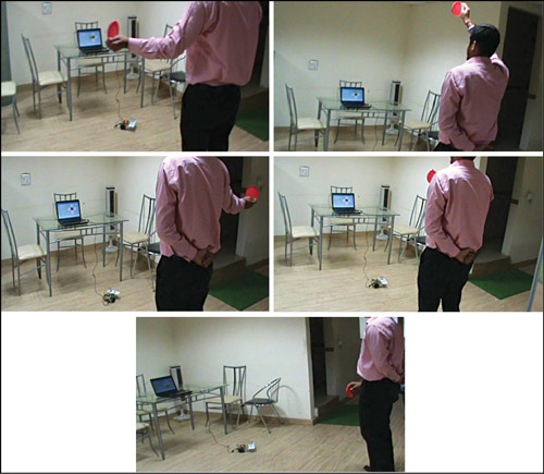
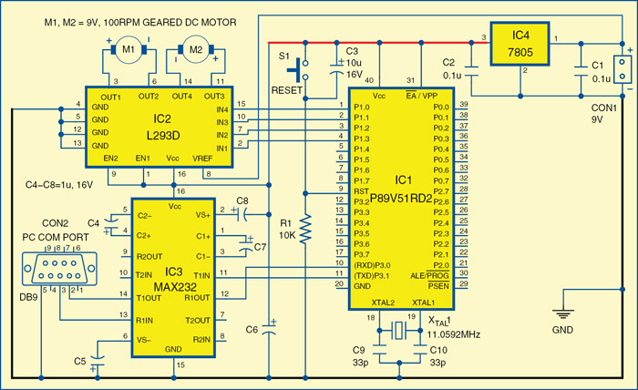
The USB port of the computer is connected to the robot through USB-to-serial converter. Controlling commands to the robot are sent via serial port and the signal levels are converted into 5V TTL/CMOS type by IC3. These signals are directly fed to microcontroller IC1 for controlling motors M1 and M2 to move the robot in all directions. Port pins P1.0 through P1.3 of IC1 are connected to the inputs of IN4 through IN1 of IC2, respectively, to give driving inputs. EN1 and EN2 are connected to Vcc to keep IC2 always enabled.

The application running on the computer interprets the position of the coloured object and sends corresponding commands to the robot through the serial port. As shown in the pictures in Fig. 1, if the operator stands in front of the computer’s camera, holds a red-coloured object in his hand and raises his hand up, the MATLAB application running in the computer interprets the position of the coloured object and sends ‘a’ to the serial port. The robot is programmed to move forward if it receives ‘a’ from the serial port. Similarly, for other positions, the letters are listed in the table, which are sent through the serial port to the robot.

The post Colour Sensing Robot with MATLAB appeared first on Electronics For You.

Accurate Electronic Stopwatch Project

$
0
0

A stopwatch is invaluable for events and time based competitions. And keeping in with today’s demand, these are available in very fancy designs and options. Presented here is a simple circuit which can be used as an accurate stopwatch that you can design for yourself and use it as and when required. It can count up to 100 seconds with a resolution of 0.01 second or up to 1000 seconds with a resolution of 0.1 second. This stopwatch can be used for sports and similar other activities.

Stopwatch Circuit

stopwatch circuit
Fig: Stopwatch Circuit

A 1MHz crystal generates stable frequency which is divided by two stages of 74390 ICs (dual decade counter) and another stage employing 7490 (decade counter) IC to obtain a final frequency of 100 Hz or 10 Hz. Due to the use of crystal, the final frequency is very accurate.

The output of IC4 (7490) is counted and displayed using IC5 74C926 (4-digit counter with multiplexed 7-segment LED driver). Due to multiplexed display the power consumption is very low. Switch S2 (2-pole, 2-way) is used to select appropriate input frequency and corresponding decimal point position to display up to either 99.99 seconds or 999.9 seconds maximum count.

For proper operation, first press switch S3 (reset) and then operate switch S2, according to the resolution/range desired (0.1 sec. or 0.01 sec.) (100 seconds or 1000 seconds). Now to start counting, press switch S1. To stop counting, press switch S1 again. The counting will stop and display will show the correct time elapsed since the start of counting.


Feeling interested? Check out our other projects!

The post Accurate Electronic Stopwatch Project appeared first on Electronics For You.

RF Signal Detector

$
0
0

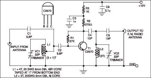
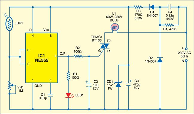
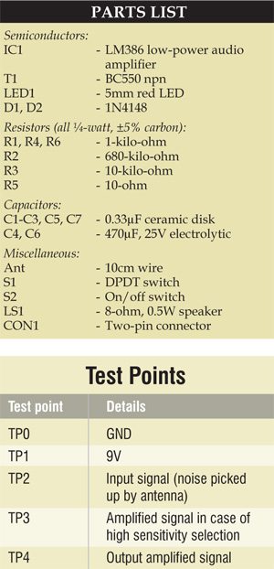
This simple RF signal detector circuit can be used to trace the presence of RF signals and electromagnetic noise in your residential area, office or shop. It can be a useful tool while testing or designing RF circuits. It can also be used to detect electrical noise in your premises.

Electromagnetic noises can be produced by sparking in electrical installations or other sources. To detect the presence of RF signal or noise, you need a wide-band receiver that can capture these signals.

Fig. 1: Circuit of RF signal detector

Circuit and working

Fig. 1 shows the circuit of RF signal detector. It consists of a telescopic antenna, input protection resistor (R1), two diodes (D1 and D2), selector switch (S1), pre-amplifier with a low-noise and high-gain transistor (T1), and audio amplifier IC LM386 (IC1).

Switch S1 is used to select between high and low sensitivities of the circuit. When high sensitivity is selected, gain of the transistor stage with T1 is added to gain of IC LM386. When low sensitivity is selected, gain of only IC LM386 is used, which is around 20. In order to keep the circuit simple and compact, no volume control is included.

D23_part-list

When there is a strong electromagnetic signal near the antenna, e.g., from a mobile phone, telephone or electrical motor, you can hear audible sound from the speaker (LS1). As you bring this detector closer to the RF or noise-transmitting source, the sound from the speaker becomes louder. Thus you can trace the exact location of the source. You can use an antenna of appropriate shape and length to increase the range of reception and sensitivity.

Construction and testing

Normally, the circuit does not need any adjustment. But it is preferable to keep the collector-emitter voltage of T1 around half the power supply voltage and the collector current at least 1 mA. The preferred power supply range is 9-15 V DC. If the circuit produces motor boating noise with AC mains adapter, use a battery instead to reduce the noise. The circuit works well with a single 9V PP3 or 6F22 type battery.

Fig. 2: An actual-size, single-side PCB for RF signal detector
Fig. 2: A single-side PCB for RF signal detector
Fig. 3: Component layout for the PCB

Download PCB component PDFs: click here

Download component layout PDFs: click here

A single-side PCB for the RF signal detector is shown in Fig. 2 and its component layout in Fig. 3. Assemble the circuit on a PCB to minimize time and assembly errors. Carefully assemble the components and double-check for any overlooked error. Use IC base for IC LM386. Before inserting the IC, check the supply voltage.

To test the circuit for proper functioning, using test points TP0 and TP1 on the PCB, first check whether power supply to the circuit is correct. Place some RF source near the antenna and through oscilloscope verify whether the signals are being received at TP2.

You can use your mobile phone as the RF source. Dial any number and place the phone near the antenna. Using switch S1 select high sensitivity for the circuit and check the amplified signal at TP3. The final output can be checked at TP4. Make sure that the RF source is continuously radiating while you check all the test points.


Feel interested? Check out more interesting project ideas in the circuit section.

The post RF Signal Detector appeared first on Electronics For You.

How to Assemble Your Own 3D Printer

$
0
0

3D printing, getting popular for making usable objects, is the reverse of traditional machining where material is removed from a block by drilling, cutting, chiseling, etc for making objects. In 3D printing, an object is created by laying successive layers of material as per requirement. This article describes how you can assemble a simple 3D printer for yourself, like we did in EFY lab, and then make use of it. But before that, you should know some basics of 3D printing.

Fig. 1: LM8UU Prusa Mendel 3D printer

The process of printing 3D objects starts with making a virtual design of the object you want to create, using one of the supported computer aided design (CAD) software. A 3D scanner can also be used to copy an existing object. The scanner makes a 3D digital copy of an object and puts it into a 3D modeling program. This 3D model file is sliced into thousands of horizontal layers which are then printed by a 3D printer, layer by layer, creating the entire 3D object. 3D printers generally employ one of below-mentioned methods.

Fig. 2: Fused deposition modeling Fig. 3: SLS system

Fused deposition modeling (FDM)

This is the most popular method used in DIY type 3D printers. Here a plastic filament or wire is made to pass through an extrusion nozzle (Fig. 2). The nozzle tip is heated to melt the filament or wire. The nozzle can be moved in all three directions, precisely, using stepper motors. The object is produced by extruding melted material to form layers upon layers of the object. The material hardens immediately after extrusion from the nozzle. The process is also known as fused filament fabrication (FFF). The printer shown in Fig. 1 is an assembled FDM based 3D printer.

Selective laser sintering (SLS)

In this method high-power laser is used to fuse small particles of plastic, metal, ceramic or glass powder to form an object. The laser selectively scans and fuses the material layer by layer as per the 3D model design. Once a layer is completely printed, the bed is lowered by one layer thickness and new layer of fused material is applied. The process is repeated until all the fused layers have been laid. Fig. 3 shows an SLS system.

Sterolithography (SLA)

This method employs ultraviolet curable photopolymer resin and an ultraviolet laser to build the object’s layers. The laser beam scans a selective surface area of the resin to solidify it as per the 3D design model. Once a layer is printed, the platform descends by a distance equal to the thickness of a single layer. And the laser scans again to print the second layer. Fig. 4 shows and SLA system.

How to build a DIY 3D printer

The printer described here is the LM8UU Prusa Mendel 3D printer. The basics of building any FDM based DIY printer will be more or less the same. The printer has three major parts: electronics (and electrical), software and mechanics.

Fig. 5 shows the complete electronic and electrical system that runs a 3D printer. Sanguinolulu board is the heart of the whole system. It controls different stepper motors for moving the nozzle in X and Y directions, moving the heat bed in Z direction and extruding the material from the nozzle.

Fig. 6 shows the stepper motors used. The board senses extruder’s and bed’s temperature through thermistors. Endstops are used (like stoppers) by the printer to determine the boundaries. Fig. 7 shows an endstop.

The temperatures of nozzle and heat-bed can be monitored through software as explained in software section. The software program, which connects to the board through USB interface, is used for loading the 3D model file for printing and testing various operations. The overall system is powered by 12V, 400W ATX power supply (Fig. 8).

Sanguinololu board

Sanguinololu board (shown in Fig. 9) is a low-cost, all-in-one electronics solution for Reprap and other CNC devices. It features an onboard Sanguino clone using the ATMEGA644P microcontroller, though an ATMEGA1284 can be easily substituted. The board is developer-friendly with expansion pins supporting I2C, SPI, UART and ADC functions. Sanguinololu has a very flexible input power supply that ranges from 7V to 30V.

Pololu board

The stepper motors are powered by Pololu boards that are mounted over Sanguinololu board. These are carrier boards or breakout boards for Allegro’s A4988 DMOS microstepping driver with translator and over-current protection. The stepper motor driver lets you control a bipolar stepper motor at up to 2A output current per coil. Fig. 10 shows a Pololu board with heatsink.

DIY 3D printer components

Heat-bed

The heat-bed (Fig. 11) normally heats up to 110°C when powered through the dedicated connection on Sanguinolou board. The power supply should be able to deliver at least 300W and wires from the power supply to the Sanguinololu board should be capable of handling 20A or slightly more current.

The post How to Assemble Your Own 3D Printer appeared first on Electronics For You.

Automatic Water Pump Motor Controller

$
0
0

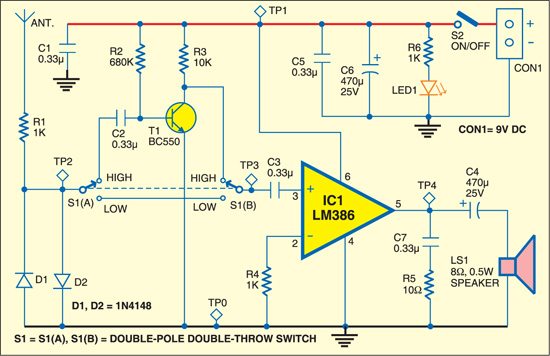
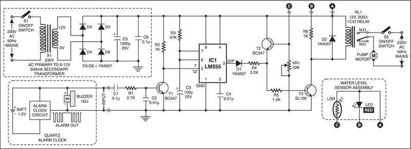
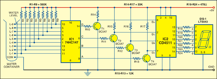
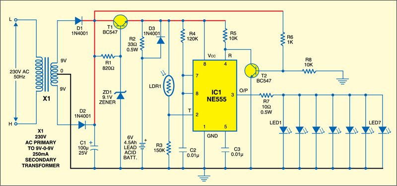
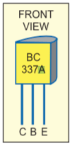
Municipal corporations in many cities supply water during early morning hours. So, you have to wake up early, just to switch on your motor pump and wait till your water tank is filled up. Further, there is no control for overflow of the tank. Many times you come to know of your overflowing tank only when your neighbor informs you. This water pump motor controller can com in handy in these cases.

Here is a low-cost and simple automatic water pump motor controller circuit (Fig. 1) to avoid the aforesaid problem. You just have to set your quartz alarm clock (connected to this system) at the appropriate time of water supply. Keep the clock nearby your sleeping bed and switch on the circuit before going to sleep. In the morning, as the alarm rings, you can switch off the alarm and, if you like, go to sleep again. The controller system will automatically switch on the pump motor immediately at the predetermined time. When the overhead tank is full, the pump motor will get switched off automatically, preventing overflow of the tank. The controller system works with a water-level sensor assembly. The sensor assembly has to be fixed up properly inside your overhead water tank.

Water pump motor controller circuit assembly

water pump motor controller circuit
Fig. 1: water pump motor controller circuit

You can assemble a simple water-level sensor (Fig. 2) at home. Take an empty cylindrical plastic vial having outer diameter smaller than 1.3 cm (0.5 inch), which is commonly used for dispensing medicines. Make it opaque by pasting a piece of black paper or PVC tape on its inner side. Fix up the vial’s lid firmly with a suitable material to make it airtight.

Now take a 15.2cm (6-inch) piece of opaque PVC conduit pipe having inner diameter of 1.3 cm (0.5 inch). Ensure that the vial can freely slide along the axis inside the conduit pipe; else use a PVC pipe having larger inner diameter. Drill two through-holes (of diameter 3.5 mm) along the diameter of the PVC pipe, at least 15 mm away from each end. Also drill two 5mm dia. through-holes along the diameter of the PVC pipe, 25-30 mm away from one end.

Insert the airtight plastic vial inside the PVC pipe and fix up two screws (M3x25mm) through 3.5mm dia. holes with suitable M3 nuts near the ends. These screws will restrict sliding of the vial within the PVC pipe.

Then fix up a 5mm red LED perpendicular to 5mm dia. hole, on the outer surface of PVC pipe, using suitable adhesive like M-seal. Also, opposite to this, fix up a light-dependent resistor (LDR) in similar way as shown in Fig. 1.

Points to consider

Ensure that both the LDR and the LED are firmly placed outside the PVC pipe and they don’t interrupt movement of the vial inside the PVC pipe.

Also ensure that the maximum light produced by the LED falls on the surface of the LDR through 5mm dia holes along the diameter of the PVC pipe. Then plug the open ends of PVC pipe with dark-coloured (preferably black) sponge pieces, to avoid ambient light entering inside the pipe.

water pump motor controller circuit implementation
Fig. 2 water pump motor controller circuit implementation

Solder the leads of LDR and LED with connecting wires of required length, according to the location of your overhead water tank. Then fix up this water-level sensor assembly vertically at a suitable height along the inner wall of the overhead water tank, as shown in Fig. 3.

Remove 1.5V (AA size) battery from the quartz alarm clock. Carefully open the back lid of the clock using a small screwdriver. Solder a braided pick-up wire parallel to the connected points of your alarm buzzer (clock). Make a small hole on the back lid of the clock and pull out free ends of the pick-up wire through this hole.

Then, carefully fix up the back lid in proper position, without disturbing any mechanical part of the clock. Solder the free ends of pick-up wire on the PCB at input terminals. This pick-up wire will provide trigger pulses from the alarm clock to water pump motor controller system. Then set the time and place the battery in alarm clock.

The post Automatic Water Pump Motor Controller appeared first on Electronics For You.

Viewing all 48 articles
Browse latest View live